Mesa Mark IIC++ JFET Replica

albatros_1994

Kungen
Joined
Jul 9, 2012
Messages
114
Reaction score
325
Location
Upplands Väsby (SE)
New project, again and again. :coffee: I want to share with the internet
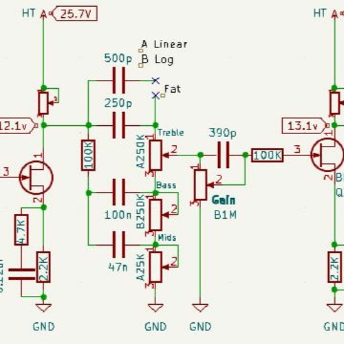
a Mesa Mark IIC++ "Replica", the preamp is really interesting as it's different from other metal amps, how good it sound even with all those stages center-biased (1.5K on the cathode almost everywhere), it's aggressive and tight without sounding muddy/fuzzy.
I used BF245Bs at 25v, they served me well on the other jfet project. I started 2-3 days ago and built the basic preamp on a prototyping board, no EQ a the beginning and no EQ a the end because i don't have the right pots and enough cables, at the moment i have a standard gain pot setup, tuned to kinda simulate having the Bass knob at 0 on the original amp, again, kinda.
I tried to bias the stages as close as possible to the original, the cathode bias caps i'm using right now are not the same as the orignal amp, but i needed to adjust the size to make it sound as it should, the total gain seems fine but i will finetune the general voicing of the stages as soon as the preamp receives a EQ, but it already sounds fine to me.
I don't own a Mark IIC++, so i'm forced to use youtube videos as reference.

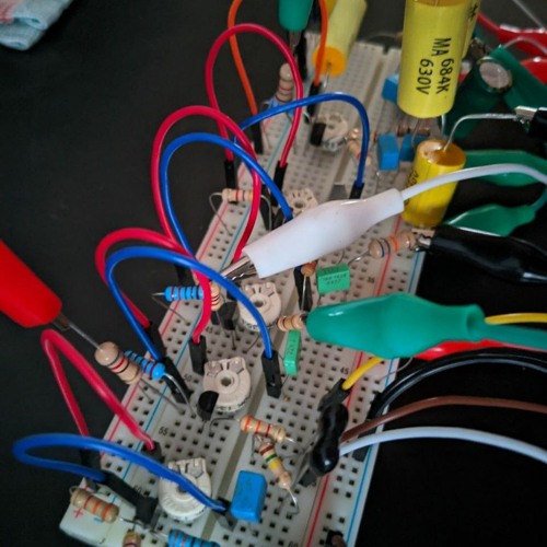
It's a total mess at the moment, but i wanted to work fast, i'll solder all on a point to point board as soon as i receive the components i need.
Here is a beta-grade schematic and really bad pictures
photo_2024-03-15_18-01-16.jpgphoto_2024-03-15_18-01-07.jpgSchematic.png

i also recorded some stuff running it through a 2xEL84 power amp, i take the signal from a load-box and that apply a slight EQ + Stereo IR (Mesa Cab + SM57 / The One + SM57), to get a realistic final-sound.


The next steps are: solder all this stuff on a real board, the two EQ, voice it "right" + finetuning, than design a faceplate.
 

This site may earn a commission from merchant links like Ebay, Amazon, and others.

complex-barb.0t

SS.org Regular
Joined
May 10, 2022
Messages
588
Reaction score
622
Also for using as a reference point, go get some IIC+ NAM profiles. That way you can at least make live comparisons when deciding what final component values you wanna use.
 

albatros_1994

Kungen
Joined
Jul 9, 2012
Messages
114
Reaction score
325
Location
Upplands Väsby (SE)
@complex-barb.0t Thank you, i don't have plans for a PCB version as everything i build is constantly getting modified, i have more freedom if i use old-school turret boards, but that said, i have the software to design that (Kicad), never actually tried. With IIC+ NAM profiles you mean plugins?
@HeHasTheJazzHands I looked at the schematics and the Mark IV is 99% a IIC+, they added extra channels and changed small things here and there but the Lead is almost the same. I mean, it's doable, i built a 3 channel amp before, but you need a lot of switches/relays to do that and i tend to keep things simple. That said, i might be able to get a something like a R2 channel just by using a switch, i'll try that.
@Hollowway Thanks, i wanna se the final result and than i will decide if it's worth it to build some clones, but i don't think i make one of these for cheaper than 200-250Euros (with a Hammond 1441-18 steel chassis and custom faceplate), it's all 100% hand-made and it takes me a week+ to make one
 

complex-barb.0t

SS.org Regular
Joined
May 10, 2022
Messages
588
Reaction score
622
@complex-barb.0t Thank you, i don't have plans for a PCB version as everything i build is constantly getting modified, i have more freedom if i use old-school turret boards, but that said, i have the software to design that (Kicad), never actually tried. With IIC+ NAM profiles you mean plugins?
@HeHasTheJazzHands I looked at the schematics and the Mark IV is 99% a IIC+, they added extra channels and changed small things here and there but the Lead is almost the same. I mean, it's doable, i built a 3 channel amp before, but you need a lot of switches/relays to do that and i tend to keep things simple. That said, i might be able to get a something like a R2 channel just by using a switch, i'll try that.
@Hollowway Thanks, i wanna se the final result and than i will decide if it's worth it to build some clones, but i don't think i make one of these for cheaper than 200-250Euros (with a Hammond 1441-18 steel chassis and custom faceplate), it's all 100% hand-made and it takes me a week+ to make one
Yeah NAM is a plugin where you load profiles like a Kemper. There are a lot of IIc profiles floating around for $0. A nice point of reference and A|B comparisons.

Here is a link to a profile. I have not tried it yet.

My favorite way to use NAM is through Two Notes Genome plugin. It has a NAM compatible block. It even includes a IIc+ profile. This plugin is free if you own various two notes products like wall of sound or a torpedo.
 

matt_boogie76

SS.org Regular
Joined
Apr 22, 2022
Messages
3
Reaction score
2
Definitely following this!

That sounds pretty awesome. I own a Mkiv rev A and it’s quite a raw sound sound as opposed the rev B i used to own.

Keep up the good work and keep updating!

Oh, i have a friend who did his own version of the boogie 5 band eq in a pedal too if that is of any interest. Can’t remember how many pcbs he had done but i can find out

🤘🏻
 

albatros_1994

Kungen
Joined
Jul 9, 2012
Messages
114
Reaction score
325
Location
Upplands Väsby (SE)
@complex-barb.0t I get it now, nice, i will absolutely look into it, interesting that they have an online version where you can load your own IRs and DIs :hbang:
@matt_boogie76
interestingly enough i've found a MK IV-A and MK IV-B lead comparison in another forum.
I think you are right, the Rev-A is probably a more aggressive/tight with maybe slighly less top-end. That C311 is doing most of the difference
MK IV-A Lead vs MK IV-B Lead.JPG
The EQ itself is not hard to build (if you skip the preamp board), pot+inductor+cap, i don't i want it that bad on my amp, but it surely is an amazing toy to have at home :agreed:
34005845453_604c35441e_o.gif
 

albatros_1994

Kungen
Joined
Jul 9, 2012
Messages
114
Reaction score
325
Location
Upplands Väsby (SE)
IMG_20240321_072327_700.jpg
Update: I moved the entire preamp from the prototyping board to a p-t-p board, as it should be. It sounds ok but i need to work on it because the the tone stack at the beginning is a fender style TMB, and it is very lossy, i'm dropping quite a bit of signal before entering the 2th stage and the gain is reduced. I will try to play around with the bypass caps to boost the gain on the later stages or increase the supply voltage to get more output swing from the JFETs but that might push the signal level too high in the preamp and clip it way to hard. I'll work on it today ;)
 

albatros_1994

Kungen
Joined
Jul 9, 2012
Messages
114
Reaction score
325
Location
Upplands Väsby (SE)
I recorded with Treble@10, Mids usually@5 or 6, Bass@0, i mostly played around with Gain and Drive in the recordings

I made some changes and tweaks:
-upped the voltage to 26-27v
-The 2nd stage has a lot more gain/output now + 100K "grid" stopper that seems to remove blocking distorsion
-100nF and 500nF caps on the 3th and 4th stage as in the IIC+ schematics (should remove some fizz/top-end)
-Source resistor slighly bypassed with a 0.1uF + 10K, to get extra gain/clipping in the high-end
I suppose it is more tight and gainy than the original amp but it sounds really great at the moment, even with a 7 string.
Still no EQ at the end of the preamp
The high noise floor should disappear as soon as i install it in a chassis with proper shielding and grounding

Schematicv2.png
 

Moongrum

Well-Known Member
Joined
Sep 7, 2013
Messages
400
Reaction score
479
Location
Pacific NW
What is the process/challenge of porting a tube schematic to a FET one?

I majored in electrical engineering, but don't pretend I remember anything from it. I recall something like FETs are more or less biased the same as tubes. Do you just drop FETs where the tubes are? Since tubes run at higher voltage, is it preferable to try to find high powered FETs or do you try to "scale" the rest of the circuit to low voltage FETs?

View attachment 140745
Update: I moved the entire preamp from the prototyping board to a p-t-p board, as it should be. It sounds ok but i need to work on it because the the tone stack at the beginning is a fender style TMB, and it is very lossy, i'm dropping quite a bit of signal before entering the 2th stage and the gain is reduced. I will try to play around with the bypass caps to boost the gain on the later stages or increase the supply voltage to get more output swing from the JFETs but that might push the signal level too high in the preamp and clip it way to hard. I'll work on it today ;)
That's wild 😂
Are you going to mount it in an amp? I'm surprised a boutique builder hasn't tried to sell p-t-p ss amps like this.
 

albatros_1994

Kungen
Joined
Jul 9, 2012
Messages
114
Reaction score
325
Location
Upplands Väsby (SE)
@Moongrum Well, i need to disclose that i have a background as electrician/automation technichan but i'm not an expert/engineer.
I'll just explain my way of thinking but i will probably be inaccurate.
In my experience FETs behaves kinda like tubes, the cathode/source resistor is gonna dictate how "early" it is gonna clip
The plate resistor in the case of tubes is mostly setting the gain, it is not doing too much as far as bias goes.
The drain resistor on JFETs does a lot, by changing that you can set the 0 point for the output signal, kinda like a DC offset in a way, and at around 50% it gives the most output swing, and if you push the input/output enough it is gonna clip on both sides of the signal. I don't need more that 10-15K to get a cold clipper, 20K+ is probably gonna clip way to early.
So you can use the drain resistor to set the gain of the stage but also decide which side of the signal you wanna clip when the output goes into "overdrive".
Now, talking about the BF245Bs i use, 1.5 to 2.2K on the source and 50-55% bias on the drain makes the output clip evenly like a tube with a 1.5K/100K setup.
Yes the tubes run at higher voltages and have bigger outputs (50-60v Vpp or maybe more) but also accept bigger signals at the input/grid. Different FETs have different max input voltage swing, the one i use seems to be fine with something like 2Vpp i think, The max allowed output voltage increases with the supply voltage.
At 25-28v with 245Bs i barely need to change the circuit of the original amp, almost a drop-in, the source bypass cap can be sensitive, i use lower values than default and limit the gain increase with a resistor in serie.
I try to make the FETs fit the schematic, instead of changing the circuit to make it work on FETs, that is what i want to say.

SS + p-t-p is weird wight? But i love how easy it is work on it and how flexible i can be with the design, i can change all i want when i want, instead of being forced to use a fixed PCB design. Not as compact and clean, but it is enough for me.
 

albatros_1994

Kungen
Joined
Jul 9, 2012
Messages
114
Reaction score
325
Location
Upplands Väsby (SE)

I played some random Metallica riffs and tried to make it sound more or less like in the recordings, less bass maybe.
I tried to recreate the GEQ of the Mark series with a standard TMB tone stack, the center of the V shape seems to peak at around 900Hz instead of 750Hz, but it's pretty close (increasing the tone-slope resistor another 10-20K should do it), i was using 220pF as the treble capacitor but i lowered it to 150pF as it seems to remove a bit more "stuff" around 2-3Khz.
The integrated 12W power amp sounds great BTW, more than enough to play at home.
Some stuff in the circuit are more similar to the original now, i'm getting closer and closer
photo_2024-04-12_10-32-23.jpgphoto_2024-04-12_10-32-35.jpgphoto_2024-04-12_10-32-42.jpg
 
Top