Petar Bogdanov
Well-Known Member
- Joined
- Feb 16, 2006
- Messages
- 1,023
- Reaction score
- 110
Some say it's made of metal... After marketing for rock didn't work.
Sadly, like most amps, the tubes are taller than the transformers. It has to be propped up to be worked on. At least the transformers are similar height.
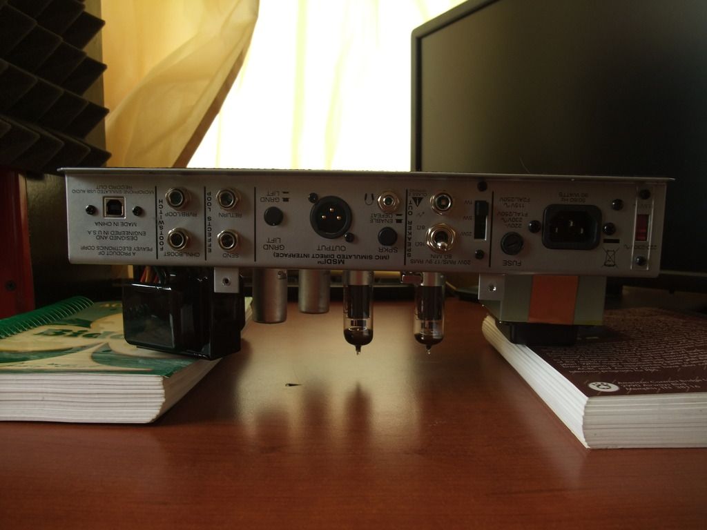
Tube layout - the preamp tubes seem to use some kind of a shielding socket. Nice.
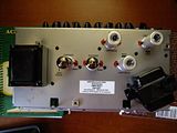
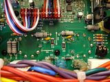
Here's the general view as seen from the back. A lot of through-hole components for the preamp section, which is nice, because it's moddable without learning to SMD. Sadly, a lot of the switching components are SMD and so is the FX loop. Better than Blackstar's approach to mini amps, but not by a huge margin. On the big daughter board (bottom centre) are attenuator and dummy load. They seem to use ceramic resistors, one might see an improvement by replacing them with metal oxide. As stock, this amp sounds best in full power mode.
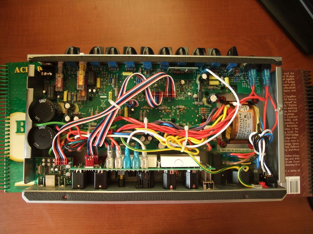
Bias adjustment is much easier with the chassis out of the shell. Without EL84 bias probes, it's the only way to go. In either case, you will need a flathead miniature screwdriver.
This is where you would measure the bias if you had no bias probes. You don't want to go to a hospital. Get it to a tech, or do it safely. Don't be a clown.
Also note the remaining soldering flux on the tube socket pins. Those joints aren't great either. Someone in China isn't taking pride in their work. Maybe they get Undercover Boss in China.
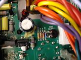
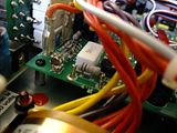
The voltage drop across R26 must be measured, in millivolts. However, it's not possible to probe its legs directly because it's SMD (thanks Peavy). It's been a few months since I've done this, but I think I measured between the left leg of F104 and R66. (as pictured)
Do not EVER think of sticking your probes into a live amp. If your multimeter has croc leads, use them! If you don't, make yourself some croc cables. Croc clips are sold in every electronics store, and you should be able to make your own cables. This is an example of a croc cable:
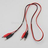
Make sure the croc tips aren't touching anything. Wrap them in electrical tape, to be sure. Make sure you're not touching any live metal while measuring the voltage. Turn on the amp and wait until the TSI leds go green. Definitely do not touch the amp now. The amp starts at a low bias and gradually increases it. Wait until it stabilizes. This amp works at 353V, so the "proper" bias range is between 24mA and 17mA. My amp was running 28mA stock, which was obviously causing crossover distortion. Not a fan. I biased it at 22mA. Now my cleans are clean and buttery.
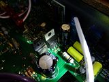
This resistor is socketed. If anyone knows why, please tell. Also shown is a fuse, of which there are 3 or 4 throughout the amp.
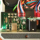
Phase inverter tu--- I mean MOSFETs. Very Blackstar. I wish the positive and negative MOSFETs matched in appearance. I hope they are matched in performance, but judging by the lack of markings, they are probably not. This might be an opportunity for upgrade, or it might be a wasted afternoon.
"Spring" reverb, as indicated on the PCB. You mean I could have had plate?! What the hell, Peavy?! Spring reverb is the worst for metal. This is the worst choice you could have made.
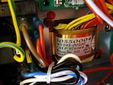
Someone was very proud of this transformer. It's for the mains.
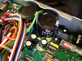
Power supply capactitors are not drainable without taking the PCB out. Working this amp is a bit sketchy. Supposedly, all 6505s have capacitor bleed resistors. I wouldn't want to find out.
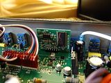
MSDI daughterboard. Note that Peavey claims the standalone MSDI is all-passive, so the chip must be for USB.
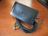
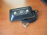
Hey, wanna hear a joke? Welded-shut plastic footswitch without rubber feet. What a piece of ..... I took off a whole star from the "quality" rating of the amp just for this thing. Adding insult to injury, it doesn't footswitch all the footswitchable features! If you want to switch all 4 things, you have to buy another of these ....s. For the lazy, the following features are footswitchable: FX Loop, Reverb, Channel, Crunch. If you want to footswitch Channel and Reverb with the same footswitch, you're out of luck.
Sadly, like most amps, the tubes are taller than the transformers. It has to be propped up to be worked on. At least the transformers are similar height.

Tube layout - the preamp tubes seem to use some kind of a shielding socket. Nice.

Here's the general view as seen from the back. A lot of through-hole components for the preamp section, which is nice, because it's moddable without learning to SMD. Sadly, a lot of the switching components are SMD and so is the FX loop. Better than Blackstar's approach to mini amps, but not by a huge margin. On the big daughter board (bottom centre) are attenuator and dummy load. They seem to use ceramic resistors, one might see an improvement by replacing them with metal oxide. As stock, this amp sounds best in full power mode.

Bias adjustment is much easier with the chassis out of the shell. Without EL84 bias probes, it's the only way to go. In either case, you will need a flathead miniature screwdriver.

This is where you would measure the bias if you had no bias probes. You don't want to go to a hospital. Get it to a tech, or do it safely. Don't be a clown.

Also note the remaining soldering flux on the tube socket pins. Those joints aren't great either. Someone in China isn't taking pride in their work. Maybe they get Undercover Boss in China.
The voltage drop across R26 must be measured, in millivolts. However, it's not possible to probe its legs directly because it's SMD (thanks Peavy). It's been a few months since I've done this, but I think I measured between the left leg of F104 and R66. (as pictured)
Do not EVER think of sticking your probes into a live amp. If your multimeter has croc leads, use them! If you don't, make yourself some croc cables. Croc clips are sold in every electronics store, and you should be able to make your own cables. This is an example of a croc cable:

Make sure the croc tips aren't touching anything. Wrap them in electrical tape, to be sure. Make sure you're not touching any live metal while measuring the voltage. Turn on the amp and wait until the TSI leds go green. Definitely do not touch the amp now. The amp starts at a low bias and gradually increases it. Wait until it stabilizes. This amp works at 353V, so the "proper" bias range is between 24mA and 17mA. My amp was running 28mA stock, which was obviously causing crossover distortion. Not a fan. I biased it at 22mA. Now my cleans are clean and buttery.
This resistor is socketed. If anyone knows why, please tell. Also shown is a fuse, of which there are 3 or 4 throughout the amp.

Phase inverter tu--- I mean MOSFETs. Very Blackstar. I wish the positive and negative MOSFETs matched in appearance. I hope they are matched in performance, but judging by the lack of markings, they are probably not. This might be an opportunity for upgrade, or it might be a wasted afternoon.

"Spring" reverb, as indicated on the PCB. You mean I could have had plate?! What the hell, Peavy?! Spring reverb is the worst for metal. This is the worst choice you could have made.

Someone was very proud of this transformer. It's for the mains.

Power supply capactitors are not drainable without taking the PCB out. Working this amp is a bit sketchy. Supposedly, all 6505s have capacitor bleed resistors. I wouldn't want to find out.

MSDI daughterboard. Note that Peavey claims the standalone MSDI is all-passive, so the chip must be for USB.

Hey, wanna hear a joke? Welded-shut plastic footswitch without rubber feet. What a piece of ..... I took off a whole star from the "quality" rating of the amp just for this thing. Adding insult to injury, it doesn't footswitch all the footswitchable features! If you want to switch all 4 things, you have to buy another of these ....s. For the lazy, the following features are footswitchable: FX Loop, Reverb, Channel, Crunch. If you want to footswitch Channel and Reverb with the same footswitch, you're out of luck.


")