joshuallen
Well-Known Member
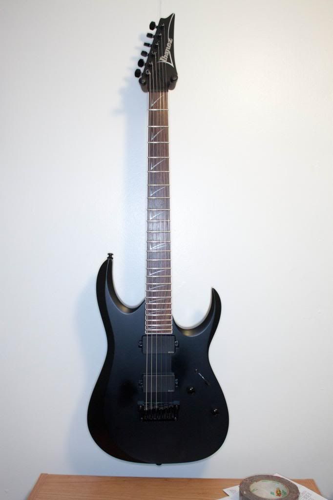
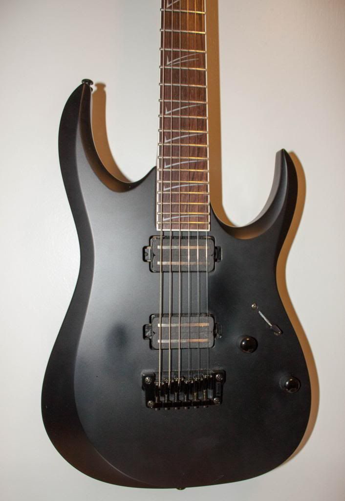
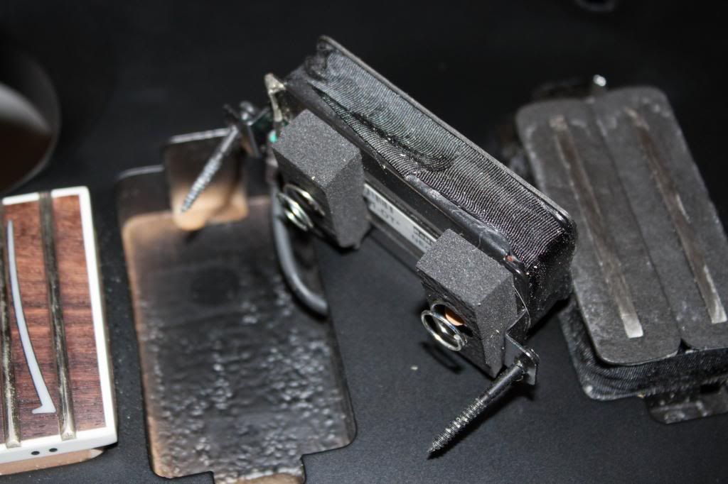
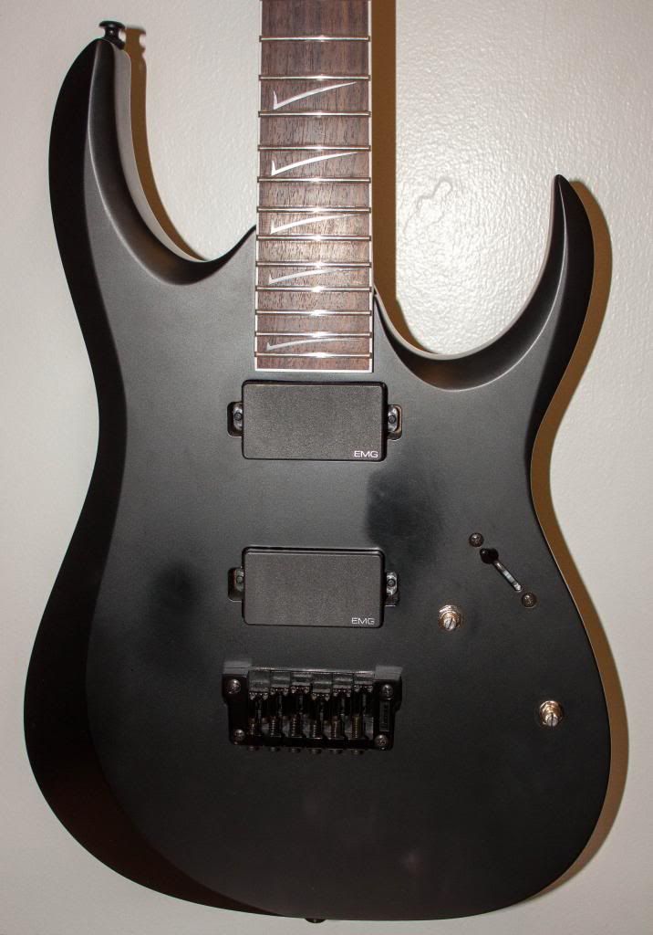
I traded out the stock VK pickups in my Ibanez RGD 321 for EMG 81/85. I went for a direct mount, which required drilling out the EMG bushings to accommodate wood screws, but I think it's good. The original VK's had foam pads and springs to offer some spring tension. I put the pads on the EMGs, but not the springs, since the EMG quick connect stuff is in the way, and I didn't want to put to much pressure on those connectors. It should work fine, but if anyone has ideas on an alternate method, I'm all ears. Haven't strung it up yet, b/c it as midnight when I got it running. The switch I had to solder, but it seems to turn on the correct pickups as expected. I also had to kind of jam the EMG outlet into the space I had, because they use a stereo plug for grounding, instead of the stock mono plug. I got it in, and it seems to work. I had to drill out the hole from the jack cavity to the rest of the cavity to get the quick connect cord through, but I only had to go up two drill bit sizes from stock, so it wasn't too bad.
Not enough room in the cavity for the 18V mod, unfortunately. I'm thinking about what I can do to make that happen. I don't now if I want to route this bad boy. I may just go with what I have. Or I could buy a clip and clip it to the edge. Seems kind of junky.
One thing I can never remember is if all the way to the right on switch is traditionally the bridge or the neck. Visually, the bridge seems more logical to me. Anyway, here are some pics:
Also, as far as the switch goes, I basically used this method:
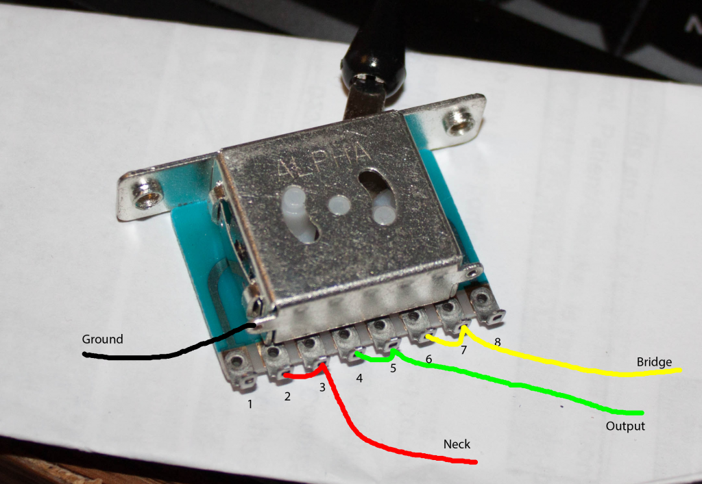
Except I connected the outside wires to the outside two terminals. From what I read, either method should work fine. What I actually wired was 1-2 Neck, 4-5 Output, 7-8 Bridge (or vice versa on Bridge/neck).
Not enough room in the cavity for the 18V mod, unfortunately. I'm thinking about what I can do to make that happen. I don't now if I want to route this bad boy. I may just go with what I have. Or I could buy a clip and clip it to the edge. Seems kind of junky.
One thing I can never remember is if all the way to the right on switch is traditionally the bridge or the neck. Visually, the bridge seems more logical to me. Anyway, here are some pics:
Also, as far as the switch goes, I basically used this method:
Except I connected the outside wires to the outside two terminals. From what I read, either method should work fine. What I actually wired was 1-2 Neck, 4-5 Output, 7-8 Bridge (or vice versa on Bridge/neck).