This is a Tech article I posted over on MG some time ago, I tried to post it here back then but was unable and forgot about it, the recent thread asking about 2027 wiring reminded me this is needed here.
Introduction
I recently discovered that there are no a wiring diagrams available to wire a HH Ibanez VLX-91 equipped guitar in the Jcustom configuration. Yes they all claim to but none of them deliver. I also noticed that Kevan's schematic also does not give you the Jcustom configuration so after discussion with Kevan I said that I would update it for him, once I started I thought why stop there and decided to do a tutorial on the VLX-91 switch.
Please note that although Kevan's schematic might be different to the configuration that is on it no one has complained, it's a combo that works and seems to produce some nice tones. It's also worth noting that if you wire your double-edge equipped guitar according to his schematic you will also get his KJG mod which has since been adopted by Ibanez.
The VLX-91
A lot of people do not like this switch because they feel it is overcomplicated, in truth it looks far more complicated than it is. There is no need to be afraid of its 24 terminals as it is really nothing more than 4 very basic switches all operated by the one selector.
Each vertical bank forms one switch and no vertical bank or switch is connected to another. The lowest terminal on each bank is always part of the circuit and each position of the switch determines which of the terminals above it will be connected to. So you have 4 paths and on each path you have 5 optional paths that you can switch to.
These following images demonstrate the 4 circuits that are created in each position.
1st or neck position

2nd position

3rd or middle position

4th position

5th or bridge position

It's that simple but by having 4 circuits at your disposal you are only limited by your imagination in terms of options although some configurations might drive you nuts trying to work out a schematic, such as the J custom wiring for example. Obviously it was too hard for Ibanez so they just told you that you had it , they did change the wiring but they finished with the same configuration.
Applying this to a Double Edge equipped Ibanez.
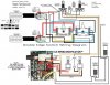
First we have Kevan's original drawing, the only changes I have made is to colour the wires and show what the different positions are giving you. This one is for Dimarzio's. Note that the wiring on this is outside to in however it is still wired out of phase so it is still hum-bucking. Also note the second position is a champion, the inside coils are connected in parallel but then they are wired in series with the coil closest to the bridge, just incase you didn't get that the inside coils are connected in parallel and then run through the bridge coil.

The next is the one I did for myself, it is for BKP's and it is J custom wiring or the wiring that Ibanez claim to have. If you wish to use it for Dimarzio's simply swap the green and the black wires.

Now if you were wondering how Ibanez have theirs wired, it is quite bizarre. It is the old HH wiring, yes even on the new ones, they changed the wire locations and ended up with almost exactly the same thing, what makes it most bizarre is the neck pickup is wired in phase, what that means is it is not hum-bucking.
This next image is my template that you can use to work out your own wiring.

Colour codes and how to wire a hum-bucker.
As I said earlier, to convert Dimarzio colour codes to BKP you simply switch the green and black. BKP wiring is as follows
Red = start of slug coil
Green = end of slug coil
Black = start of screw coil
White = end of screw coil.
Stewmac has a great reference for other manufacturers colour codes and can be found here Free information at Stewart-MacDonald
The way we apply these colour code is like this. You can wire in phase or out of phase. Out of phase means that they are wired to cancel hum, in phase means they will not cancel 60 cycle hum. To wire out of phase in series the start of the slug coil goes to the switch, the start of the screw coil goes to ground and you connect the other two wires together. To wire in phase in series the start of the slug coil goes to the switch, the end of the screw coil goes to ground and you connect the other two wires together.
So if we call the start + and the end - we get this
In Series
Hum-bucking +--+
Non Hum-bucking +-+-
In parallel
Hum-bucking +- connected at each end
Non Hum-bucking ++ at one end and -- at the other.
Hopefully this makes it a little easier to wire your new set of BKP's the way you want with your VLX-91.
Finally please note that I did not create these images, they are Kevans work that I have simply modified the wiring for the VLX-91 switch, the KJG mod (named after Kevan, der) is Kevans work which Ibanez went on to use in future double edge equipped models. I'm sure most of the members here knew that already. Cheers.
Introduction
I recently discovered that there are no a wiring diagrams available to wire a HH Ibanez VLX-91 equipped guitar in the Jcustom configuration. Yes they all claim to but none of them deliver. I also noticed that Kevan's schematic also does not give you the Jcustom configuration so after discussion with Kevan I said that I would update it for him, once I started I thought why stop there and decided to do a tutorial on the VLX-91 switch.
Please note that although Kevan's schematic might be different to the configuration that is on it no one has complained, it's a combo that works and seems to produce some nice tones. It's also worth noting that if you wire your double-edge equipped guitar according to his schematic you will also get his KJG mod which has since been adopted by Ibanez.
The VLX-91
A lot of people do not like this switch because they feel it is overcomplicated, in truth it looks far more complicated than it is. There is no need to be afraid of its 24 terminals as it is really nothing more than 4 very basic switches all operated by the one selector.
Each vertical bank forms one switch and no vertical bank or switch is connected to another. The lowest terminal on each bank is always part of the circuit and each position of the switch determines which of the terminals above it will be connected to. So you have 4 paths and on each path you have 5 optional paths that you can switch to.
These following images demonstrate the 4 circuits that are created in each position.
1st or neck position
2nd position
3rd or middle position
4th position
5th or bridge position
It's that simple but by having 4 circuits at your disposal you are only limited by your imagination in terms of options although some configurations might drive you nuts trying to work out a schematic, such as the J custom wiring for example. Obviously it was too hard for Ibanez so they just told you that you had it
, they did change the wiring but they finished with the same configuration.Applying this to a Double Edge equipped Ibanez.
First we have Kevan's original drawing, the only changes I have made is to colour the wires and show what the different positions are giving you. This one is for Dimarzio's. Note that the wiring on this is outside to in however it is still wired out of phase so it is still hum-bucking. Also note the second position is a champion, the inside coils are connected in parallel but then they are wired in series with the coil closest to the bridge, just incase you didn't get that the inside coils are connected in parallel and then run through the bridge coil.
The next is the one I did for myself, it is for BKP's and it is J custom wiring or the wiring that Ibanez claim to have. If you wish to use it for Dimarzio's simply swap the green and the black wires.
Now if you were wondering how Ibanez have theirs wired, it is quite bizarre. It is the old HH wiring, yes even on the new ones, they changed the wire locations and ended up with almost exactly the same thing, what makes it most bizarre is the neck pickup is wired in phase, what that means is it is not hum-bucking.
This next image is my template that you can use to work out your own wiring.
Colour codes and how to wire a hum-bucker.
As I said earlier, to convert Dimarzio colour codes to BKP you simply switch the green and black. BKP wiring is as follows
Red = start of slug coil
Green = end of slug coil
Black = start of screw coil
White = end of screw coil.
Stewmac has a great reference for other manufacturers colour codes and can be found here Free information at Stewart-MacDonald
The way we apply these colour code is like this. You can wire in phase or out of phase. Out of phase means that they are wired to cancel hum, in phase means they will not cancel 60 cycle hum. To wire out of phase in series the start of the slug coil goes to the switch, the start of the screw coil goes to ground and you connect the other two wires together. To wire in phase in series the start of the slug coil goes to the switch, the end of the screw coil goes to ground and you connect the other two wires together.
So if we call the start + and the end - we get this
In Series
Hum-bucking +--+
Non Hum-bucking +-+-
In parallel
Hum-bucking +- connected at each end
Non Hum-bucking ++ at one end and -- at the other.
Hopefully this makes it a little easier to wire your new set of BKP's the way you want with your VLX-91.
Finally please note that I did not create these images, they are Kevans work that I have simply modified the wiring for the VLX-91 switch, the KJG mod (named after Kevan, der) is Kevans work which Ibanez went on to use in future double edge equipped models. I'm sure most of the members here knew that already. Cheers.