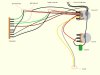
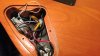
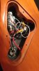
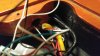
Hello, I have been looking into adding a blow switch in the form of a push-pull tone pot on my Yamaha 821DX, and have been wracking my brains over how to do the wiring properly. I haven't been able to find any original wiring diagrams for the guitar, so I have gone through all the connections and created an image, as well as a few reference photographs. For reference, the pickup configuration is H-S-H with 1 vol, 1 tone and a 5 way blade. The pickups are DiMarzio Air Classic humbuckers with a DiMarzio Blue Velvet single coil. Would it be as simple as rewiring the 1/4 jack input through the switch, as well as the bridge pickup hot so as to either pass through as normal or isolate the single pickup on push/pull? I assume since that sounds simple it cannot be correct. Any input at all would be much appreciated.
You are using an out of date browser. It may not display this or other websites correctly.
You should upgrade or use an alternative browser.
You should upgrade or use an alternative browser.
Wiring for a blow switch
- Thread starter venrar
- Start date
This site may earn a commission from merchant affiliate links like Ebay, Amazon, and others.
This site may earn a commission from merchant links like Ebay, Amazon, and others.
marcwormjim
Well-Known Member
You have the right idea. I don't know what kind of experience you have; so apologies if I over/under-explain this:
A double-pole, double-throw (DPDT) switch is like a switcher on a set of train tracks: The signal is always routed one of two ways. The difference is that you have the option to funnel two signals into one track, if you want.
Of the six contacts/lugs on the switch, the middle two are always "on"/connected, with the switch selecting between which of the outside sets of lugs are paired with the middle ones.
Note: You will need at least a few inches of new wire for the mod.
To achieve a push/pull tone pot blower-switch,
1. Unsolder the wires and capacitor from the old tone pot one at a time, soldering them to the same place on the three lugs of the new push-pull pot before you unsolder and resolder the next wire. I recomend using a knife to scuff up the side of the push-pull pot; to make it easier to solder the ground wire to it.
2. Find the wire coming from the middle lug of the volume pot. If it's connected to a ground wire from the bottom of the volume pot (as is common in factory wiring), this will be annoying: You must separate the two; either by replacing both the lead and ground wires with new ones, or using a razor or stripper to cut the insulation holding the two together along their path from the volume pot to the jack. If the ground wire is bare, it will need to be reinsulated or replaced along its length from the volume pot to the jack.
3. If the factory lead/hot wire running from the middle lug of the volume pot to the jack is long-enough, you can snip it in the middle and wire it into the push-pull pot. If you have ANY doubt that it is long enough, use a new length of wire that's cut to your needs.
4. Solder one end of a lead/hot wire between the middle lugs of the switch, and the other end to the hot sleeve of the output jack. This is your track out of the switch. If you're using the factory wire that you cut in half, just solder the hot wire that was already connected to the jack to the middle lugs of the switch.
5. Solder the hot wire from the middle lug of the volume pot to the bottom set of lugs on the push-pull. This ensures that, when the push-pull is down, the guitar functions as normal.
6. Find where the hot wire of the bridge pickup connects to the pickup selector switch. You will need to use a length of extra wire to solder to the same contact/lug that the pickup lead/hot wire is soldered to. If it's easier, you can unsolder the pickup hot wire, braid it together with the new wire, and then solder the joint wires back onto the lug on the selector switch. The extra wire you added is what's known as a "jumper."
Then, solder the other end of the jumper across the top set of lugs of the push-pull. These are the outside lugs that will be combined with the middle set when you pull up on the push-pull.
From there, just reassemble everything. Note that it is not 100% necessary to wire everything across two lugs of the push-pull - It just makes for a stronger connection that is less-likely to come unsoldered when you're reassembling.
In case it isn't obvious, make sure you have every ground wire running the same as you did before. By the end, you may have had to replace the ground wire running between the bottom of the volume pot and the ground-sleeve of the jack.
Once you understand how the signal-path works, you'll see other possibilities for routing with a push-pull: You can use it to put the bridge and neck pups in parallel or series, bypass the tone pot, have sex with my wife, add in extra capacitors or resistors to reshape the tone of a pickup, etc.
TonyFlyingSquirrel
Cherokee Warrior
Yup, Marc has ya covered.
I use an emery board to scuff the back of the pot, but same principle.
I use an emery board to scuff the back of the pot, but same principle.
Marc, thank you for the explanation, it's perfectly detailed, and will definitely make this process a lot easier. And thanks for the tip on the emery board Tony. It's been a few years since I have warmed up the soldering iron, so lets see if I can't go and make a bunch of cold joints.