[Urgentish] Pots won't fit!

  • Thread starter TauSigmaNova
  • Start date
  • This site may earn a commission from merchant affiliate links like Ebay, Amazon, and others.

7stg

Well-Known Member
Joined
Sep 15, 2007
Messages
1,621
Reaction score
156
Location
WA
I don't have a multimeter and I'm running low on my guitar budget after the pickups, soldering gear, extra wires, and etc. Might just consider taking it to a pro next week and just paying them copious amounts of money to fix it all. I'm using a stereo plug- did I solder to the wrong hot output? There was two and I soldered to one of them. Should I have soldered to the other?

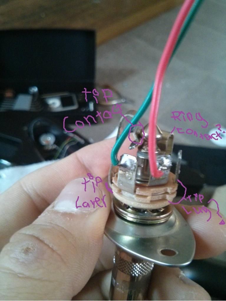
This is one of the things the multimeter will help with. Standard guitar plugs are a TS plug. The Tip is the positive, and the Sleeve is ground. It's easiest with a multimeter to test continuity with a guitar cord in the jack put a probe on the tip and then put a probe on a lug on the back of the jack, if the meter beeps you found the right lug. Alternatively, if you can find a diagram of your jack on line you can follow that.

How are your soldering skills?
Here is a good lesson Basic Soldering Lessons 1 - 9 - YouTube

My suggestion to Learn is get that 22awg stranded wire, strip 3/8 - 1/2 inch, apply electronic flux, tin the wire, and then snip it off. Repeat 20-30 times paying attention to how the solder flows and getting the right amount of solder on the wire.
 

7stg

Well-Known Member
Joined
Sep 15, 2007
Messages
1,621
Reaction score
156
Location
WA
Jack wiring.
Tip is hot. The contact touching the tip which is behind the green wire needs to be connected.

With a stereo jack there will be connectors for The Ring and Sleeve, both will contact the Sleeve on a TS plug so functionally it does not matter which you use. If you can tell which contact is further back that is the proper one to use to be technically correct.
 

This site may earn a commission from merchant links like Ebay, Amazon, and others.

7stg

Well-Known Member
Joined
Sep 15, 2007
Messages
1,621
Reaction score
156
Location
WA
So confused. What do I need to do?

If you followed standards and used red for hot move the red wire to connect to the solder lug for the piece that touches the tip. In the picture behind the green wire there is the contact physically touching the tip. That is the hot connection. It does not look connected, it may have its solder lug on the other side which is not connected.
 

TauSigmaNova

Guitarist Wannabe.
Joined
Nov 24, 2013
Messages
759
Reaction score
241
Location
New York City
If you followed standards and used red for hot move the red wire to connect to the solder lug for the piece that touches the tip. In the picture behind the green wire there is the contact physically touching the tip. That is the hot connection. It does not look connected, it may have its solder lug on the other side which is not connected.
The green is around the lug without the ring so i think the green is the hot and it connects to a lug on the volume pot.

I posted s picture of the elec. Cavity if it help, it shows where everything connects.

Sorry if all this is supposed to be obvious - I'm a complete and utter noob when it comes to any of this. Just someone who wanted to change the pickups in his guitar without the knowledge or tools to do any of it :p
 

7stg

Well-Known Member
Joined
Sep 15, 2007
Messages
1,621
Reaction score
156
Location
WA
The green is around the lug without the ring so i think the green is the hot and it connects to a lug on the volume pot.

I posted s picture of the elec. Cavity if it help, it shows where everything connects.

Sorry if all this is supposed to be obvious - I'm a complete and utter noob when it comes to any of this. Just someone who wanted to change the pickups in his guitar without the knowledge or tools to do any of it :p
The green wire is currently soldered to the lug that is one layer above the layer that the tip is going too. it needs to be moved down one layer.

jack_zpsc2fadf75.jpg


Here is the diagram for the whole schematic.
Wiring Diagram
 

TauSigmaNova

Guitarist Wannabe.
Joined
Nov 24, 2013
Messages
759
Reaction score
241
Location
New York City
The green wire is currently soldered to the lug that is one layer above the layer that the tip is going too. it needs to be moved down one layer.

jack_zps3be48f74.jpg


Here is the diagram for the whole schematic.
Wiring Diagram

That's the diagram I've been using, just adapted for DiMarzio coloring for the neck. So pretty much solder it to the right of the red wire, not the left?
 

7stg

Well-Known Member
Joined
Sep 15, 2007
Messages
1,621
Reaction score
156
Location
WA
That's the diagram I've been using, just adapted for DiMarzio coloring for the neck. So pretty much solder it to the right of the red wire, not the left?

I think so. I can't fully see that the tip lug comes out there, but if it does that is where you want to solder.
 
Top