adrock
long ball larry!
I tried posting this in the workbench, but no permission there. I guess a mod will move this there? hopefully.
so my initial thread was kind of a fail, due to shipping delays, and other difficulties. I also thought, hey, why not write a picstory so people can see what goes into assembling a pedal. so here we go.
I've looked at a few sites for diy pedal supplies. but I, like a few of you I'm sure, am pretty broke these days. sure kits are nice, but I don't have $100 for that. I do have some basic electrical knowledge though, and that alone can save you tons, as I will show here.
I decided to go with francisco at tonepad for my pcbs. one of the main reasons I went with the pcbs from tonepad is the price, and quality. I paid $28 for two boards shipped to my house. I don't need to pay a company to pick and sort all of the other components for me. I can do that myself. I placed an order with small bear for everything else I needed, except enclosures, and paid $40 total. shipped to my house. we're at a grand total of $68 for two pedals. not too bad. I already had my enclosures, but simple ones can be had at small bear, already painted, for $10-$15. that would work out to be a "custom" pedal, for like $45...
another reason i went with tonepad is the PDFs supplied that go with the pcbs. here is a link to the one for the tubescreamer for example: http://www.tonepad.com/getFile.asp?id=81
they are laid out extremely well. each component is labeled clearly. the schematic is included right there in one PDF with the parts list. it just makes everything simple when it comes to assembly time.
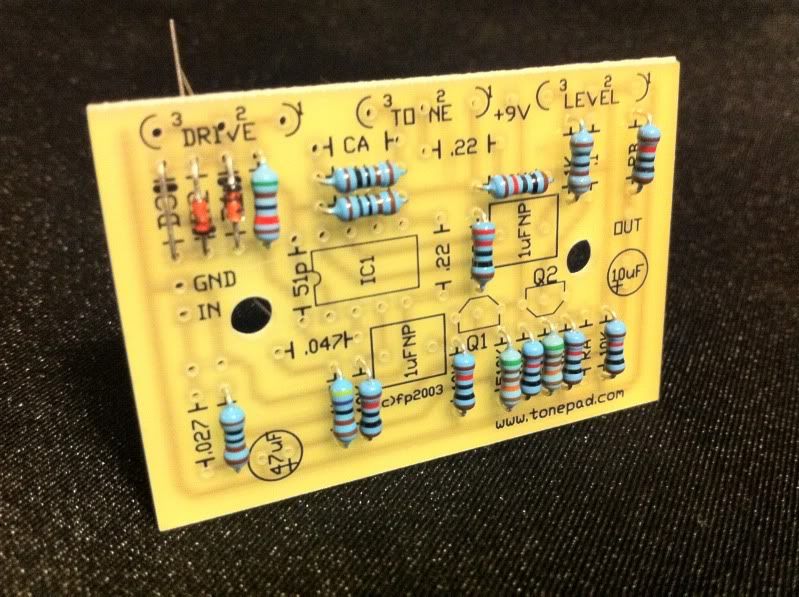
the pcbs themselves are extremely high quality, clean layout, and compact. if you take your time, check everything three or five times, these will work on the first try. mine did. here is the side that receives the components:
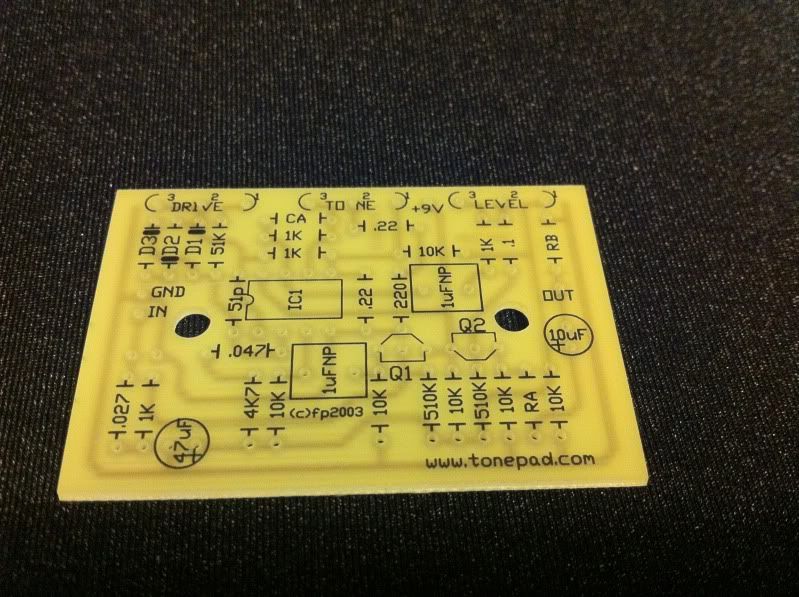
everything is labeled so clearly. matches with their pdf perfectly. just enough room for the parts. niccce
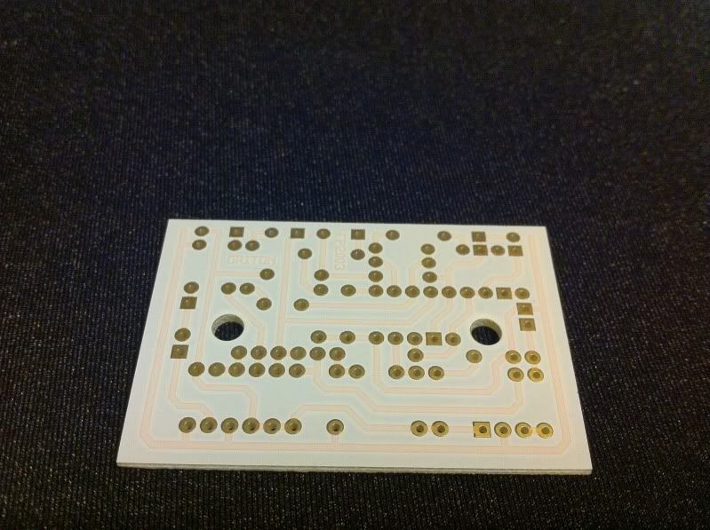
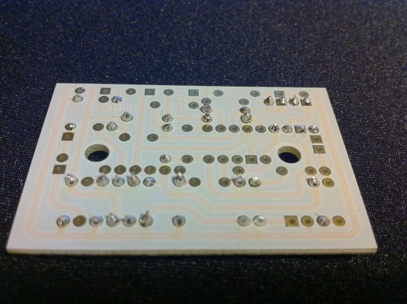
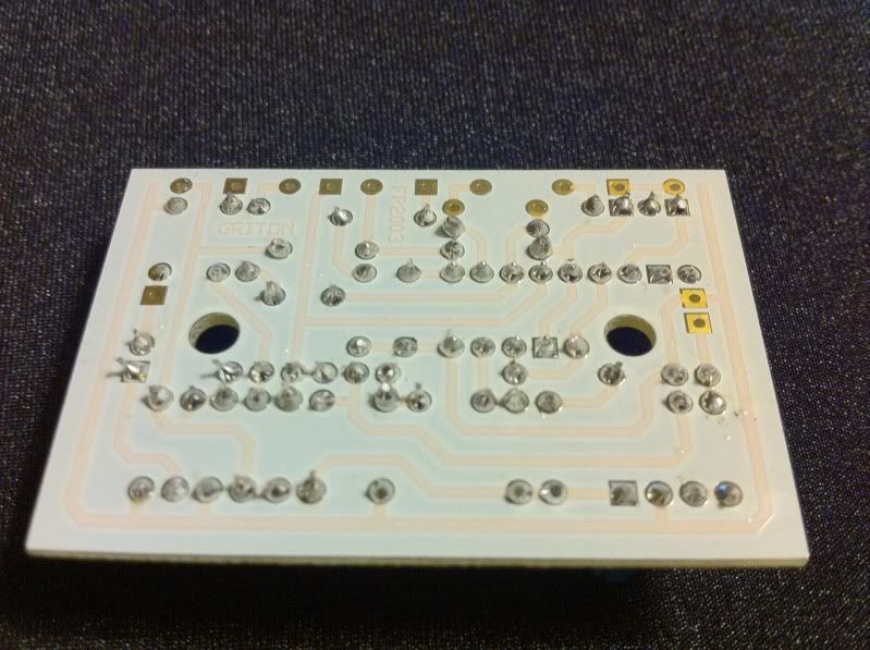
here is the solder side. nice solder pads, makes soldering quick and easy:
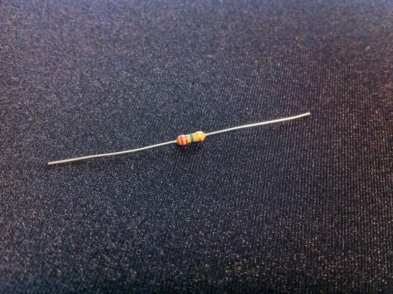
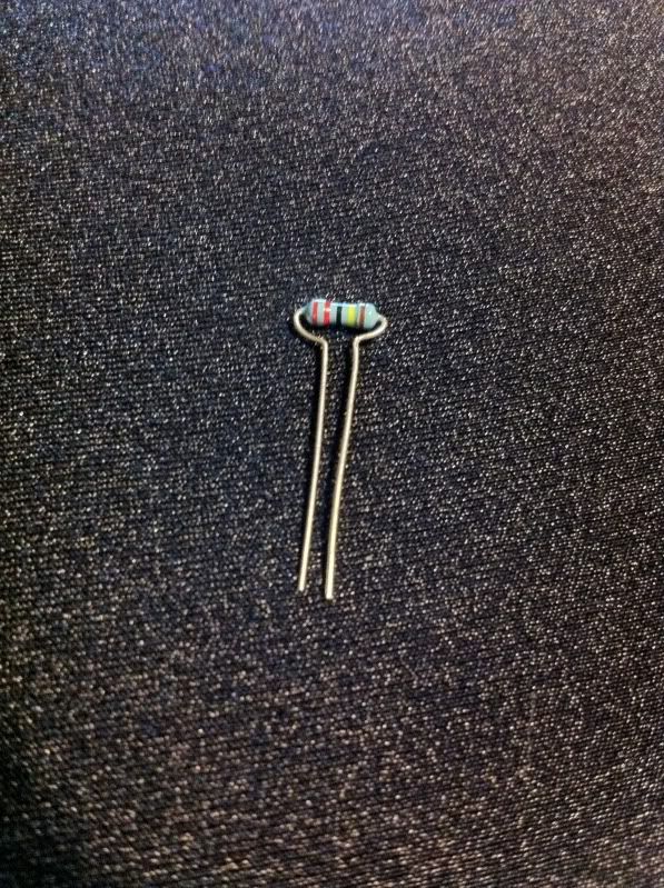
the first components installed should always be the smallest ones. start with any diodes or resistors you have. they come like this, with their leads straight. this is a resistor:
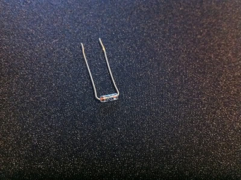
you wanna bend the leads on resistors to a right angle, right where it meets the actual component. on these pcbs, and most others, this will make them slide right in. this is a diode, ready to install:
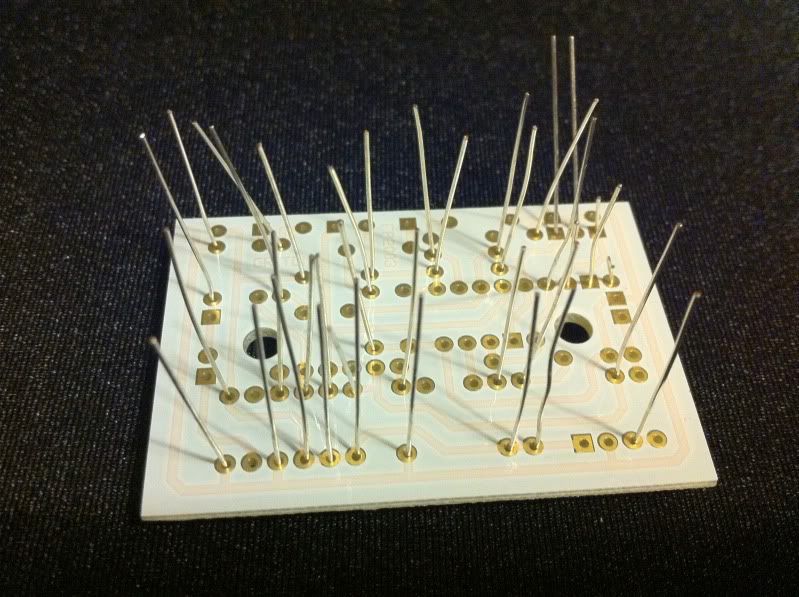
I like to put all of the components in that I can at the same time, so when I go to solder, I can just do them all at once. here's the component side, ready for phase one of soldering:
here the the solder side, ready for solder. it looks a little crazy, but just start on one end and work across:
when it becomes too tight for your iron, snip a couple of leads, and continue. here is phase one, all done. my snips suck, so please excuse the nasty looking lead cuts. it's just cosmetic:
phase two would be any ic chips you'd have. some analog delays can have up to 10-12!! this only has one. I use sockets to protect the chip from heat damage from soldering, and to make chip swapping easy. no picture. it's only one component!!
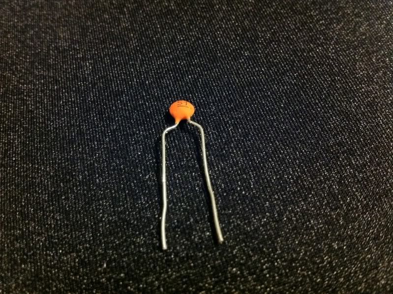
next up is phase three, capacitors. the lead spacing on your board will alway determine how you wanna bend the leads on your components. resistors and diodes are easy. on almost any kind of capacitor, besides radial, you'll have to get creative to make them fit. needle nose pliers make this easy work. here's a tiny ceramic capacitor, custom bent to fit the board:
this board requires a resistor to be custom bent as well:
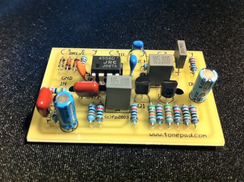
here is the board with all of the on-board components installed:
now that all of the on-board components are installed, it's time to cut some wire for the off-board components. switches, jacks, and potentiometers, or pots for short. I started with the pots, but it doesn't really matter in the end. whatever works. here is my enclosure, scored off of craigslist for about $3.50:
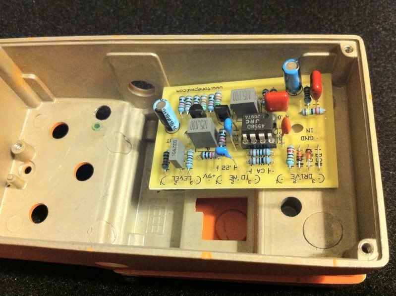
place your board and components in the enclosure where they will be mounted. here is my board in the enclosure:
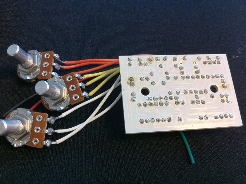
then measure and cut each piece, adding an inch or so for stripping, and a little slack. here is the board with pots and wires soldered on:
at that point in the build I realized a few wires were too short, and I installed a wrong size capacitor. hence the dark regions on the solder pad side. my iron is a bit hot for this work, and caused the board to discolor when I was removing solder. it's all good though, just a testament to the quality of tonepad pcbs!! haha..
anyways, here is the board in the pedal, getting it ready and measuring the wires for the switch and power supply:
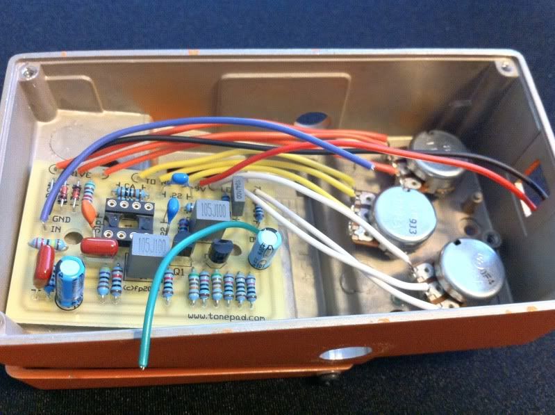
and here is the board with all off-board components wired and soldered in place. besides the power supply jack. I ordered the wrong size, so it's just kinda sitting in there for now:
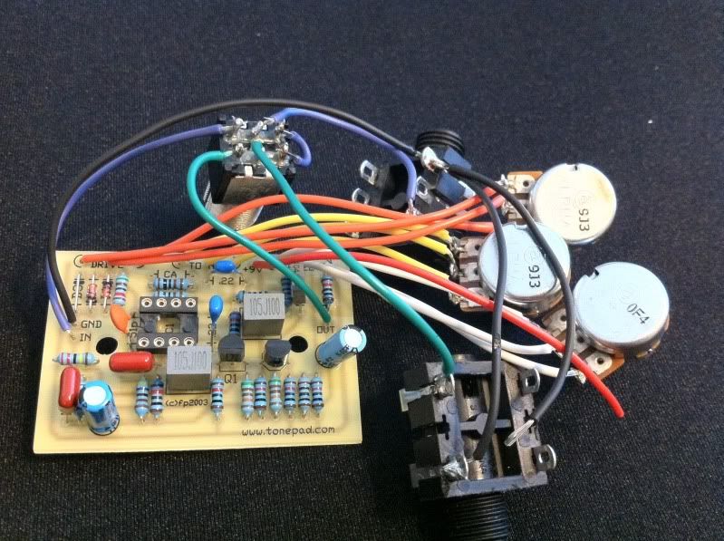
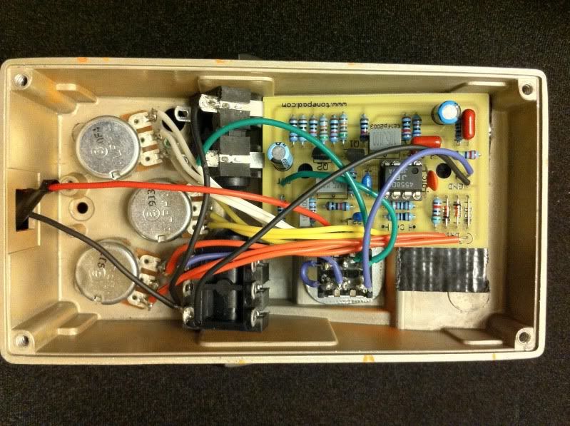
now all that's left is installing the pots, switch, and jacks into the enclosure. I was fortunate in this build. everything fits in very snug, so I don't need to actually bolt the board in place. the tension from the wires, and the physical dimensions of the case will hold it in place. here is the inside, ready to rock!!
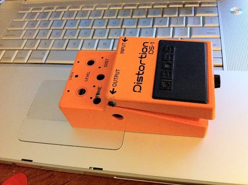
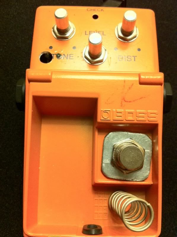
I was also very fortunate with the switch. I was able to sandwich the enclosure with two washers that will hold the switch in place. one on either side. you can see one in the previous picture if you look closely. here is the top side:
I really love this, as it's a total sleeper at the moment. is that a ds-1 or a ts808?
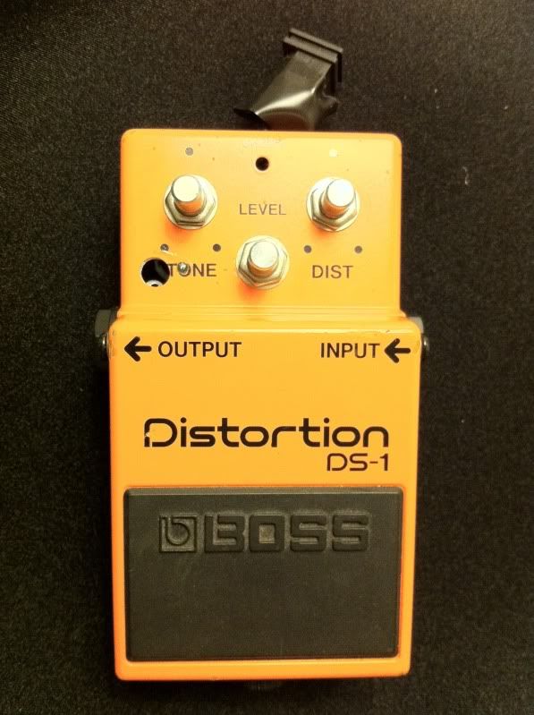
it's definitely not a tweek on the go pedal, so no knobs for now. waiting for another order to small bear for a new power supply jack. also going to throw a status led in there when I swap the power jack. but other than that, I plugged it in and it worked beautifully on the first stomp!!! like I said, check everything five times before plugging it in, and it will work..
I hope you enjoyed this, and it helps someone out there. please feel free to ask me any questions. I'll do my best to help as much as I can..
so my initial thread was kind of a fail, due to shipping delays, and other difficulties. I also thought, hey, why not write a picstory so people can see what goes into assembling a pedal. so here we go.
I've looked at a few sites for diy pedal supplies. but I, like a few of you I'm sure, am pretty broke these days. sure kits are nice, but I don't have $100 for that. I do have some basic electrical knowledge though, and that alone can save you tons, as I will show here.
I decided to go with francisco at tonepad for my pcbs. one of the main reasons I went with the pcbs from tonepad is the price, and quality. I paid $28 for two boards shipped to my house. I don't need to pay a company to pick and sort all of the other components for me. I can do that myself. I placed an order with small bear for everything else I needed, except enclosures, and paid $40 total. shipped to my house. we're at a grand total of $68 for two pedals. not too bad. I already had my enclosures, but simple ones can be had at small bear, already painted, for $10-$15. that would work out to be a "custom" pedal, for like $45...
another reason i went with tonepad is the PDFs supplied that go with the pcbs. here is a link to the one for the tubescreamer for example: http://www.tonepad.com/getFile.asp?id=81
they are laid out extremely well. each component is labeled clearly. the schematic is included right there in one PDF with the parts list. it just makes everything simple when it comes to assembly time.
the pcbs themselves are extremely high quality, clean layout, and compact. if you take your time, check everything three or five times, these will work on the first try. mine did. here is the side that receives the components:
everything is labeled so clearly. matches with their pdf perfectly. just enough room for the parts. niccce
here is the solder side. nice solder pads, makes soldering quick and easy:
the first components installed should always be the smallest ones. start with any diodes or resistors you have. they come like this, with their leads straight. this is a resistor:
you wanna bend the leads on resistors to a right angle, right where it meets the actual component. on these pcbs, and most others, this will make them slide right in. this is a diode, ready to install:
I like to put all of the components in that I can at the same time, so when I go to solder, I can just do them all at once. here's the component side, ready for phase one of soldering:
here the the solder side, ready for solder. it looks a little crazy, but just start on one end and work across:
when it becomes too tight for your iron, snip a couple of leads, and continue. here is phase one, all done. my snips suck, so please excuse the nasty looking lead cuts. it's just cosmetic:
phase two would be any ic chips you'd have. some analog delays can have up to 10-12!! this only has one. I use sockets to protect the chip from heat damage from soldering, and to make chip swapping easy. no picture. it's only one component!!
next up is phase three, capacitors. the lead spacing on your board will alway determine how you wanna bend the leads on your components. resistors and diodes are easy. on almost any kind of capacitor, besides radial, you'll have to get creative to make them fit. needle nose pliers make this easy work. here's a tiny ceramic capacitor, custom bent to fit the board:
this board requires a resistor to be custom bent as well:
here is the board with all of the on-board components installed:
now that all of the on-board components are installed, it's time to cut some wire for the off-board components. switches, jacks, and potentiometers, or pots for short. I started with the pots, but it doesn't really matter in the end. whatever works. here is my enclosure, scored off of craigslist for about $3.50:
place your board and components in the enclosure where they will be mounted. here is my board in the enclosure:
then measure and cut each piece, adding an inch or so for stripping, and a little slack. here is the board with pots and wires soldered on:
at that point in the build I realized a few wires were too short, and I installed a wrong size capacitor. hence the dark regions on the solder pad side. my iron is a bit hot for this work, and caused the board to discolor when I was removing solder. it's all good though, just a testament to the quality of tonepad pcbs!! haha..
anyways, here is the board in the pedal, getting it ready and measuring the wires for the switch and power supply:
and here is the board with all off-board components wired and soldered in place. besides the power supply jack. I ordered the wrong size, so it's just kinda sitting in there for now:
now all that's left is installing the pots, switch, and jacks into the enclosure. I was fortunate in this build. everything fits in very snug, so I don't need to actually bolt the board in place. the tension from the wires, and the physical dimensions of the case will hold it in place. here is the inside, ready to rock!!
I was also very fortunate with the switch. I was able to sandwich the enclosure with two washers that will hold the switch in place. one on either side. you can see one in the previous picture if you look closely. here is the top side:
I really love this, as it's a total sleeper at the moment. is that a ds-1 or a ts808?
it's definitely not a tweek on the go pedal, so no knobs for now. waiting for another order to small bear for a new power supply jack. also going to throw a status led in there when I swap the power jack. but other than that, I plugged it in and it worked beautifully on the first stomp!!! like I said, check everything five times before plugging it in, and it will work..
I hope you enjoyed this, and it helps someone out there. please feel free to ask me any questions. I'll do my best to help as much as I can..